|


|
 
 
Please choose from the following links to find assembly instructions for your product. Please review your kit when you get it to make sure you have all the parts listed. Take note that some parts illustrated in the assembly instructions may have changed due to availability and tweaks in the unit.
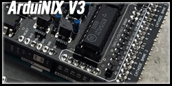 |
Step by step instructions to assemble and test your ArduiNIX V3 kit
The ArduiNIX V3 features Analog 0-5, GND, Reset, SCL, SDA, AREF, 5V, TX and RX broken out to an input/output section of headers at the front of the board near the cathode bank. All the same parts as V1 and V2 are used |
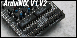 |
Assemble and test your ArduiNIX V2 or V1 kit - OBSOLETE
The ArduiNIX V2 features Analog 0-5 broken out to an input/output section of headers at the front of the board near the cathode bank.
(ArduiNIX V1 and V2 is discontinued, please refer to the V3 instructions) |
 |
Instructions, tips and tricks to assemble the ArduiNIX IN-12 display kit
Supported code available here. |
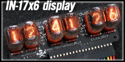 |
Instructions, tips and tricks to assemble the ArduiNIX IN-17 display kit
This is also handy information for any other configuration of IN-17 tubes, 4, 6 or 8. |
| |
|
| |
|
|
 |