|
V3 Assembly Steps: 0 1 2 3 4 5 6 7 8 9 10 11 12 13 14 15 16 17 18 19 20 21 22 23 24 25 26 27
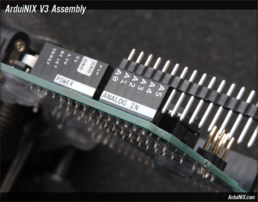
Step 21: Pin Rail Assembly: Power Side = 40 Pin 2.54mm Single Row Breakaway Header Pin Rail Use the Arduino as a guide for placement and orientation to get the rails in straight. First, place six pins on the end of the pin rail into the ANALOG IN section of the Arduino.
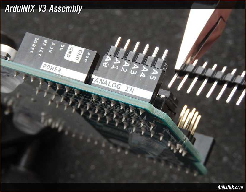
With a pair of needlenose pliers or cutters, cut the rail at the sixth pin, and move the six-pin rail from the ANALOG IN header over to the POWER header.
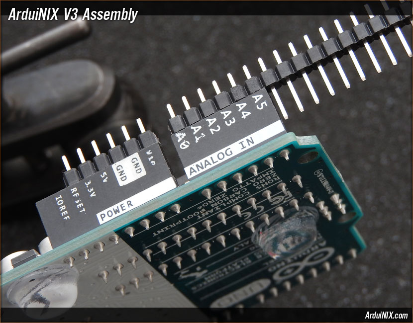
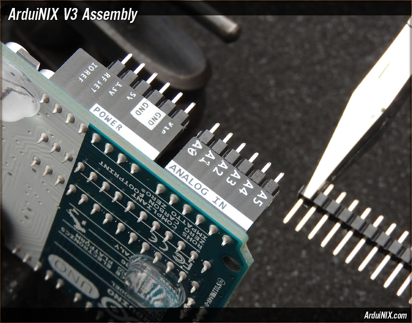
Only six pins are needed in the ANALOG IN and POWER sections. Cut the rail after the sixth pin past A5, and the rails for the power side are complete.
The rest of the pin rail will be used on the data side on the opposite side of the board. V3 Assembly Steps: 0 1 2 3 4 5 6 7 8 9 10 11 12 13 14 15 16 17 18 19 20 21 22 23 24 25 26 27 |
|
|
|
The ArduiNIX is a RobotPirate Project; a nonentity production : Questions? Email Bradley |
||