|
V3 Assembly Steps: 0 1 2 3 4 5 6 7 8 9 10 11 12 13 14 15 16 17 18 19 20 21 22 23 24 25 26 27
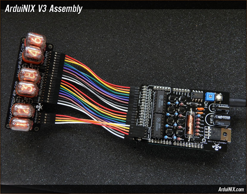
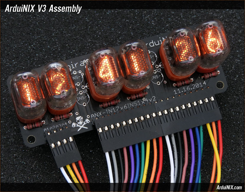
Step 27: Download Code - 6 Nixie Tubes and 4 Nixie Dots (For colons) Now download the code, upload it to your Arduino, and attach the tubes, lamps, or tube board to your ArduiNIX. If you have purchased and assembled an IN-17x6 kit, now is the time to attach it to the cathodes and anodes. V3 anode labels A1 through A4 correspond to the anode labels on the display board. However, if your codebase differs, or if you are running a V1 or V2 ArduiNIX Shield, and you are seeing out of place digits, invert one side of the anode cable, so that:
Please note: Anode configurations are not hard wired. They can be output in any sequence via code.
Now that your ArduiNIX is fully functional, the next steps are up to you. Make a clock, a timer, a web hit counter. Attach a GPS, or real-time clock. Hook up buttons and LEDs to the input/output section to control your nixie tube display. Build a box, and take photos and post it all on the Robotpirate forums! V3 Assembly Steps: 0 1 2 3 4 5 6 7 8 9 10 11 12 13 14 15 16 17 18 19 20 21 22 23 24 25 26 27 |
|
|||||
|
The ArduiNIX is a RobotPirate Project; a nonentity production : Questions? Email Bradley |
||||||