|
IN-12x6 Board Assembly Steps: 0 1 2 3 4 5 6 7 8
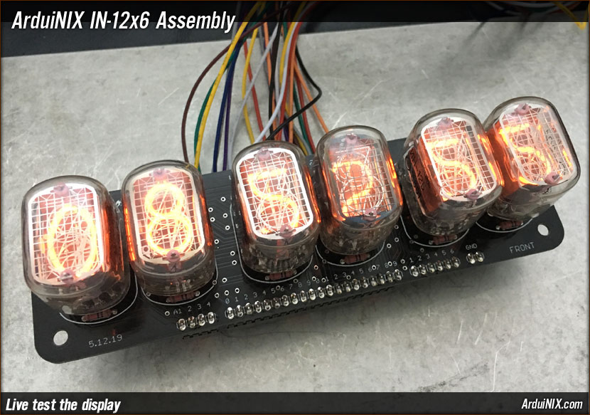
Step 8: Test At this point, the board is ready to test. The anode and cathode headers may be connected to the ArduiNIX shield via cable/wires, and with proper code, tested. The 1 through 5 pins after the cathode section are for grounding out to the GND section if decimal places for each of the tubes in the case of using IN-12b tubes. In that case one pin from GND needs to go back to GND on the ArduiNIX shield. |
|
|
|
The ArduiNIX is a RobotPirate Project; a nonentity production : Questions? Email Bradley |
||